• Welcome to the Two Wheeled Texans community! Feel free to hang out and lurk as long as you like. However, we would like to encourage you to register so that you can join the community and use the numerous features on the site. After registering, don't forget to post up an introduction!

PCP & PCM pins on Honda ECU - help!!

Joined
Apr 22, 2011
Messages
3,338
Reaction score
396
Location
Princeton, Texas
First Name
Gary
Last Name
Waugh
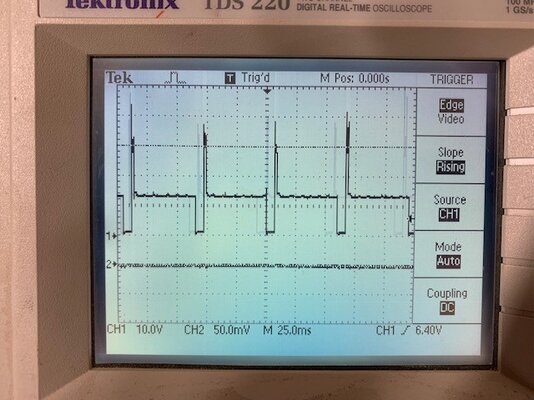
Okay guys, I am fitting a combination speedo/rev counter to my wife’s 2020 CRF250F, I have wired it up correctly and the unit powers on and seems to work. However the engine RPM is reading half what it should be, ie the engine is running at 4,000RPM but the rev counter shows 2,000RPM. I have confirmed the unit is set up for a single cylinder, but I suspect they are expecting it to be a single cylinder 2 stroke not 4 stroke (so one spark every revolution of the crank, rather than the 1 spark every 2 revolutions that a 4 stroke has). The rev counter is connected to the low voltage side of the ignition coil and works perfectly except for it showing half the actual engine RPM. I looked at the wiring diagram for this bike and there is an ignition pickup that will see a pulse once every revolution of the crankshaft, however it’s an inductive pickup and the 2 ends of the pickup connect to 2 pins on the ECU. One pin is marked PCM and the other pin is marked PCP, I have no idea what these acronyms mean and don‘t know which end I should try connecting to the rev counter to see if it will show the correct RPM. I will get an oscilloscope and check the signals (once my garage has got a bit warmer) but I was hoping someone on here might be able to tell me what the 2 acronyms mean, I would expect one end of the pickup coil to connect to a virtual ground and the other no to pulse up and down as the trigger on the crankshaft passes the pickup, but which pin is the ground and which is the actual signal? We have a lot of mechanics on here, so hoping someone might be able to tell me before I dig the scope out and freeze trying to check the signals!! I have also contacted the rev counter manufacturer, but they are Chinese so I don't expect much help!!
Regards Gary
 
I would be more concerned about tapping into that pin without using an ultra-high-impedance buffer, since that likely is attached to a hall effect pickup, and by overloading the pin, you can screw up the signal and perhaps make it unusable for the intended use. You will certainly change waveshape so the slope is too shallow and the PCM input will trigger late, and you might load it down enough to reduce the voltage enough to not reach the threshold voltage to trigger the input correctly. On top of that there's signal quality issues like noise. I wouldn't screw with it if I were you.

I would wait for a response from the manufacturer. But if they don't respond, you could double the sensor frequency by putting in a bridge rectifier, as long as each polarity of the sensor voltage exceeds the forward bias voltage of the diodes you choose. It will reduce the sensor peak to peak voltage by half, so you might wind up with an insufficient signal. Other ways to do it, of course, but this is by far the simplest IMHO, even if you had to put an active circuit there to amplify the signal.

Leave it to the guitar amp designer to find analog problems with digital circuits. :)
The additional load of the rev counter on those 2 pins is one of my concerns, the service manual clearly shows the pickup to be an inductive coil, not a Hall effect device (it also has only 2 connections, not 3 that a hall device requires), but loading either of those ECU pins could have an undesirable effect!!
 
Whatever type of magnetic sensor it is, it is a reactive device which depends on a known LRC in order to provide the correct signal. Introducing a parallel load, again an unknown LRC circuit, is going to have an effect no matter what. Whether it has a meaningful effect, or results in poor reliability, is unknown.

At this point I'd also be worried about feedback on the circuit from the input of the tach. Depending on the type of circuit in the tach, it may very well have a current spike that creates noise or standing waves or who knows what that represents as signal-level noise on the ECU inputs. Consider the tach, it's intended to take a signal from an inductive pickup which is applied to a ultra-high-impedance circuit (the spark plug wire, typ), and that circuit is essentially immune to noise due to a gross impedance mismatch. So they would never be concerned about signal degradation of the input signal. It's not a bus.

Anyway. I'd make up a bridge rect. and try that while you're waiting on the mfr to reply. Make it up with Shottky diodes and it should provide very low voltage drop. Still could be a signal level problem, get your scope on it and see what you have to work with.
 
If it's possible, set it up for a twin.

If my math is correct, I think this would result in making the problem worse by a factor of two.

The problem seems to be that the Honda is not waste spark. It doesn't fire every 360 degrees, which would result in a useless spark on the exhaust stroke. Any old school crank triggered single will fire every 360 degrees. I would guess the Honda has a camshaft-driven phase sensor so it can detect 720 degrees of crankshaft rotation and only fires the ignition on the power stroke.

In less time than it took me to make these replies, I could have whipped up a bridge rectifier and filter to provide a frequency-doubled input to the tach. Most of my time would have been spent crimping connectors. If you are willing to cut wires and solder it inline, then a quad of Shottky diodes and a little electrolytic cap, $2 worth of parts and a little solder, and a coupla pieces of heat shrink and Bob's your uncle.
 
If it's possible, set it up for a twin.
I have confirmed it is setup for a single, even the manufacturer looked at the setup (I supplied a picture of the options page on the tacho) and confirmed it is in single cylinder mode. They are investigating (or so they claim).
 
If my math is correct, I think this would result in making the problem worse by a factor of two.

The problem seems to be that the Honda is not waste spark. It doesn't fire every 360 degrees, which would result in a useless spark on the exhaust stroke. Any old school crank triggered single will fire every 360 degrees. I would guess the Honda has a camshaft-driven phase sensor so it can detect 720 degrees of crankshaft rotation and only fires the ignition on the power stroke.

In less time than it took me to make these replies, I could have whipped up a bridge rectifier and filter to provide a frequency-doubled input to the tach. Most of my time would have been spent crimping connectors. If you are willing to cut wires and solder it inline, then a quad of Shottky diodes and a little electrolytic cap, $2 worth of parts and a little solder, and a coupla pieces of heat shrink and Bob's your uncle.
I agrée with you, trouble is I don’t have any Schottky diodes lying around!! Need to order some, but where are you adding the capacitor? I am familiar with a bridge rectifier, but how and where are you suggesting the filter goes? Is this a low pass filter? High pass? Smoothing filter (can’t see that! I want the tach to see the pulses, not smooth them out!!)? Do you have a schematic or can you describe the filter that you are suggesting?
regards Gary
 
I'd be concerned that the gap between peaks would be too narrow for the tach to detect at high RPMs, so I'd consider AC-coupling it with a series capacitor as a HPF. I'd need to measure the input resistance of the tach to calculate the value. IDK the rpm range of your bike, but if you want the tach to work reliably from say 2K to 8K, then obv. tune the filter for 5kHz. Turns out that'd be a ceramic cap or maybe a polyester film in the range of like 68pF to maybe 0.01uF depending on the input resistance.

The more I think about it, the more I think the tach is almost certainly AC coupled at the input anyway so you probably don't have to worry about the capacitor, and just a bridge would get the job done. I suggest Shottky diodes due to low drop out, since you are cutting the AC signal in half to begin with just with the bridge so that extra 0.7V of a normal silicone diode might be too much. This is all the wrong analog signal and who knows how it is treated at the input, and a lot of assumptions here.
 
well I don't have any Schottky diodes, so I tried connecting a regular bridge rectifier to see what would happen, unfortunately it didn't work. Basically one side of the input coil is connected to ground (Negative) and the other side is pulsed by the ECU, I get a nice pulse arriving at the input to the coil, I connected the 2 ac inputs of the bridge rectifier to the 2 input pins on the ignition coil (so one side was ground and the other is pulsed). I then connected the + output of the bridge rectifier to the tach input pin, and connected the -ve output of the bridge rectifier to ground. Started the engine, but it shows exactly the same revs, I put the scope on it to see if I could see the back EMF pulse (the second pulse I was hoping the bridge rectifier would direct to the +ve output) but there is no second pulse, I suspect the ECU probably ahs a back EMF diode inside it, so that is effectively removing the back EMF pulse!! Still trying, but looks like I will need to use an active circuit to generate the second pulse, or modify the insides of the tach to half it's range (so 4K RPM appears as 8K RPM)!!
 
It's because you grounded the -ve output. You effectively shorted half of the bridge.

Did you look at the input signal on a scope? It occurs to me that this is not a regular analog CPS-triggered ignition, but an ECU output, which probably goes high, then drops on schedule, and then after some time less than 360 degrees of crankshaft rotation it goes back high to charge the coil. So the duty cycle is way more than 50%, in which case a bridge rect wouldn't work anyway. It'd just make it constantly high. If you put a square wave into a bridge rectifier you get DC out.

Anyway, here's hoping the manufacturer gives you an answer. Sorry to waste your time with the bridge. I should have considered before that this was a likely >50% duty cycle square wave.

This is why I should stay in my lane. :)
 
I did connect the scope to it, you can basically see that the line sits at 12 volts and is pulsed to ground when the spark pluig is fired and the signal then returns to 12 volts (with about 25 volt overshoot/ringing) ready for the next pulse.. The ground reference is the little arrow on the left side with the number 1 by it, its on 10 volts per cm.
The manufacturer does not want to fix the issue, they are just offering me a 50% refund as the unit mostly works!! I am going to create a frequency doubler using two monostables to create an extra pulse. I opened the speedo but it has a couple of dedicated chips and some tiny surface mount resistors, but without a schematic I have no idea how to modify it, so the pulse doubler seems the best bet!! More work that I wanted, but it keeps me busy!!

Regards Gary
 

Attachments

  • IMG_3224.jpg
    IMG_3224.jpg
    111 KB · Views: 71
Right on. Yeah, that's what I was afraid of, it stays high and then drops to fire, recovers nearly immediately. A bridge would just turn that into DC with a ton of switching noise.
 
I also connected my scope to the 2 pins on the ECU (PCM & PCP) to see if they could be used to trigger the rev counter, but although it shows the pickup as a simple inductive pickup in the schematic, the ECU is sending out a varying DC level with pulses on the PCP pin to one side of the pickup and then the PCM signal has the induced signal plus the pulses from the PCP pin, the waveform is completely unusable by the rev counter. Just for interest i connected the rev counter to the PCM pin, and it immediately showed more than 10K RPM whilst the engine was idling (all the pulses from the PCP pin are being registered by the rev counter). I didn't like the idea of using these pins (no idea what it might do to the ECU behavior) but this has proved that it's not an option!! Still no idea why they pulse one side of a pickup coil, obviously the ECU needs the pulses, but I have no idea what they do with them!!
 
Many thanks for the link, unfortunately the circuit that they show is limited to a very symmetrical input waveform (my ECU waveform is not symmetrical (50/50 duty cycle) at all) also the PLL that they use is expecting a constat Input frequency which it can then double, according to the PLL spec sheets it won’t allow a 5x change in frequency (reving the engine from 1,800 RPM to 9,000 RPM is a 5x change in speed/freq).
i will definitely play with it, I have a very similar idea using two monostables, but thanks for sharing.
Gary
 
Last edited:
Wait a minute. Which Honda is this on? Maybe the ECU has a tach output ... my Triumph does, so does my Vespa.
If it does, Honda don’t show it in their wiring diagram. The ECU has 33 pins but only about 20 seem to be used, maybe one of the unused pin is a tacho output? But how to find out? It’s a 2020 CRF250F, the part number is 38770-K99-A01. I looked at my CRF450L workshop manual it's a different ECU, but the PCM and PCP pins are the same number so maybe Honda has a standard pin out, unfortunately the 450 doesn't have a tacho, so no pinout is shown in the schematic!! Any suggestions how to get a list of pin functions for an ECU? I tried doing a WEB search to see if other motorcycle models used the same ECU, hoped one model would have a tacho and I could look at the wiring diagram to see the tacho pin, but WEB search doesn't seem to be able to find other models that use this part number ECU.
 
Last edited:
I'd look for a street bike with the same engine. Like for Asian market. Might have a tach. Or just put your oscilloscope probe on each of the unused pins and see if any have a sine wave or square wave on them.
 
I'd look for a street bike with the same engine. Like for Asian market. Might have a tach. Or just put your oscilloscope probe on each of the unused pins and see if any have a sine wave or square wave on them.
The problem with checking the ECU pins, it that the plug that goes on is sealed and does not have the pins for the unused ecu pins, so it will be very hard to connect to any of the unused pins and check the waveforms on them..
 
well, a little forward progress, although I couldn't find another motorcycle that used the same ECU, it appears that the 33 pin plug that Honda uses to connect to the ECU is also used to connect to other Honda motorcycle ECU's. The manufacturer for the plug list 6 honda models, 4 of them don't have tachometers, but 2 (CBR600 & CBR1000 (2010-2013)) both have tachos. I found wiring diagrams for both bikes and the tacho is connected to pin 17 on those ECU's, if I am lucky honda has standardized the pin out. When I look at my ECU, pin 17 is not used!! So maybe that is also a tacho output on my ECU? Unfortunately I tried to connect my scope to the pin to see if there is a waveform present, but its a sealed waterproof plug and I cannot get anything into the sealed pin location that can contact the pin coming out of the ECU!! I have ordered a replacement plug from the manufacturer, $10 and when that arrives I will try to open the existing plug and see if I can actually make contact to pin 17!! So all is not lost, but it's going to cost me $10 and a weeks wait to find out!! :)
 
That's good news. And right proper tech snooping there. This kind of thing is how we got a mod to get rid of the low-voltage starter cutout on Triumphs and a ton of other useful mods.
 
Monostables to generate a 2nd pulse might work, but check the timing at max rpm. At 6000 rpm, a 4 stroke with 1 pulse per 2 revs would have a pulse period of 20 ms, and a 2 stroke would have 10 ms. So your ~7 ms pulse width, when a second is added, would overlap the next revolution. You might have to shorten each pulse width. If you go this route, you might test the tach with a pulse generator to ensure it operates properly with narrower pulses.
 
Monostables to generate a 2nd pulse might work, but check the timing at max rpm. At 6000 rpm, a 4 stroke with 1 pulse per 2 revs would have a pulse period of 20 ms, and a 2 stroke would have 10 ms. So your ~7 ms pulse width, when a second is added, would overlap the next revolution. You might have to shorten each pulse width. If you go this route, you might test the tach with a pulse generator to ensure it operates properly with narrower pulses.
The pulse from the ecu is 5ms wide and doesn’t seem to change as I rev up the engine. At 10,000rpm, I have a 12ms cycle time, so my thinking is I have the existing 5ms pulse and that leaves 7ms, so I wanted a 2ms delay, then a 3ms wide pulse and that leaves 2ms before the next 5ms pulse arrives!! If my maths is correct, 5 + 2 + 3 + 2 should equal 12ms so it should all work up to 10k rpm. The engine is limited to 9500 rpm so fingers crossed it all works out.. of course if the pin 17is a tacho output, then I won’t need any of the monostables!! 😁
 
As I understand it, the bike at 10,000 rpm = 167 rev/s, or 6 ms/rev. The 4-stroke spark is every other rev, so 12 ms pulse period. However, you need to fool a tach designed for a 2-stroke, which needs a pulse per rev, or 6 ms pulse period. So, the original 10,000 rpm pulses were 12ms: 5ms low, 7 ms high, must now be 6ms: 5ms low, 1ms high, or else shorten the low pulse. You can do this with 555's but it will take care. Good luck.
 
Back
Top